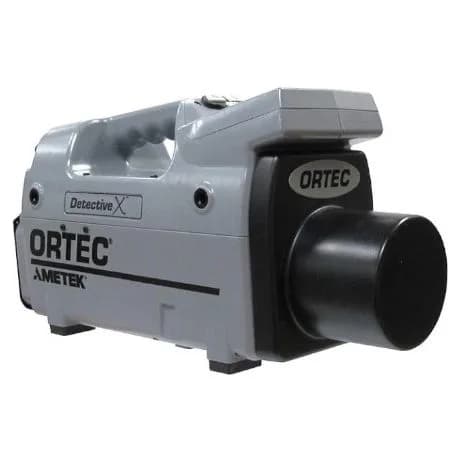
DSPEC-50A & DSPEC-502A
- Constructeur
- Ortec
- Réf. HTTS
- HTS-NUC-0066
- Réf. HTDS
- LE DSPEC 50A DSPEC 502A
- Division
- Nucléaire & Radioprotection

Galerie et schémas techniques


Description
Les DSPEC-50A et DSPEC-502A soulignent le progrès constant du matériel ORTEC pour atteindre une instrumentation nucléaire innovante et de haute qualité permettant aux scientifiques de travailler sur un large éventail d’applications dans le monde. Salué par ses performances et sa grande stabilité, ces modèles sont disponibles en version Standard et Advanced. Tous deux offrent le même traitement et la même stabilité du signal numérique pour des performances spectroscopiques optimales, tandis que les modèles Advanced intègrent des fonctionnalités permettant d’optimiser les applications de synchronisation des signaux, telles que la suppression Comptons et les mesures en anti-coïncidences. Les performances communes sont : Avantages:
Electroniques de traitement de signal pour des performances spectroscopiques optimales
Caractéristiques
- Gamme d’énergie étendue : 64k canaux
- Gamme fenêtre de coïncidence : -6.375 à +6.375 µsec
- Largeur de fenêtre : 0 à 200 µsec
- 4 sorties OutPut différentes (Passeur, CRM, SCA, ADC Gate)
- Pilotable via logiciel de spectrométrie gamma LVIS
- Ajustement auto du pole zéro et la ligne de base
- Correction auto du temps mort
- List Mode
- Stabilisateur digital du spectre
- Optimisation automatique des paramètres de traitement
- Alimentation interne
Spécifications techniques
- DSP
- 50/50A and DSP 502/502A
- COAX
- 187 keV to 24 MeV
- Gain
- <50 ppm/°C. [Typically <30 ppm/°C.]
- Gate
- Same options as standard (Off, Concidence, and Anticoincidence)
- NRTL
- Certification verifies, through OSHA-approved NRTL certification base/preamplifier/bias supply for NaI detectors with 14-pin, 10 stage
- LO-AX
- 94 keV to 12 MeV
- Model
- Description
- Power
- DIMS for non-SMART-1 detectors are available with the following high
- Offset
- <5 ppm/°C of full scale, with Rise and Fall times of 12 μs, and Flat
- Weight
- of a Detector Interface Module or “DIM” with 2 m cables. The DIM has a
- DIM-296
- Detector Interface Module with Model 296 ScintiPack tube
- Display
- 7” backlit color LCD provides status information. Displayed Inputs and Outputs
- GLP/SLP
- 16.5 keV to 2 MeV
- IGLET-X
- 8 keV to 1 MeV
- USB 2.0
- Universal serial bus for PC communications. detector; therefore, the high voltage can be turned on.
- ADC Gate
- Output when Gate is active
- DSPEC 50
- 11 kg (24.25 lbs). mating connector for the traditional detector cable set: 9-pin D preamp
- DSPEC-50
- DSPEC 50 with MAESTRO Software, single MCA, and single internal High Voltage Power Supply.
- Detector
- Multipin connector (13W3) with the following:
- Analog In
- Normal amplifier input.
- DIM-NEGGE
- Detector Interface Module for ANY Non-SMART-1 negative
- DIM-POSGE
- Detector Interface Module for ANY Non-SMART-1 positive
- DSPEC 502
- 11.7 kg (25.8 lbs). power cable, Analog In, Shutdown In, Bias Out, and Inhibit In.
- DSPEC-502
- DSPEC 502 with MAESTRO Software, two MCAs, and two internal High Voltage Power Supplies.
- DSPEC-50A
- DSPEC 50 (Advanced) with MAESTRO Software, single MCA, and single internal High Voltage Power Supply.
- Fine Gain
- 0.5 to 1.1. with rise times less than the selected Flat Top Time setting and exponential
- Flat Tops
- 0.3 to 2.4 in steps of 0.1 μs.
- Ratemeter
- Count-rate display on MCA and/or PC screen.
- DSPEC-502A
- DSPEC 502 (Advanced) with MAESTRO Software, two MCAs, and two internal High Voltage Power Supplies.
- Dimensions
- 42.55 cm W x 35.56 cm D x 15.24 cm H
- Inhibit In
- Rear-panel BNC connector accepts reset signals from transistor- The remote shutdown may be set to ORTEC or TTL mode via computer
- Rise Times
- 0.8 μs to 23 μs in steps of 0.2 μs.
- ADC Gate In
- Rear-panel BNC accepts slow positive NIM input; computer Negative Output: Rear-panel SHV connector, –500 to –5 kV. Computer
- Coarse Gain
- 1, 2, 4, 8, 16, 32, 64, and 128. Analog In: Rear-panel BNC accepts preamplifier signals of either polarity,
- DSPEC-UPG-A
- Upgrade of DSPEC-50 to DSPEC-50A or DSPEC-502 to DSPEC-502A.
- Shutdown In
- Rear-panel BNC is used to turn off the bias supply voltage in
- Preamp Power
- 1 W maximum (+12 V, –12 V, +24 V, –24 V, 2 GND).
- Change Sample
- Output on software command for Sample Changer operation
- Input Voltage
- 100–220 V AC. voltage options:
- Preamplifiers
- Computer selectable as either resistive or TRP preamplifier.
- Gate Route Mode
- Coincidence and Anticoincidence data collected concurrently. Both spectra and the
- Input Frequency
- 47–63 Hz.
- Positive Output
- Rear-panel SHV connector, +500 to +5 kV. Computer
- Sample Ready In
- Rear-panel BNC connector, accepts TTL level signal The SHUTDOWN input is clamped at –700 mV by an internal clamp. For
- • Gate Window
- Defined by delay after coincidence detection and gate restorer rate (High, Low, and Auto). (Patented.)
- Preamp Power Out
- Rear-panel, 9-pin D connector; provides ±24 V and
- Change Sample Out
- Rear panel BNC connector, TTL compatible. supply should be off.
- Operating Systems
- Windows 10, 8.1 and 7 via CONNECTIONS. bias HPGe detector.
- USB 2.0 Connection
- For use when connecting one or more DSPEC 50 or connectors:
- also be displayed.
- The “Big Numbers” Display.
- Ethernet Connection
- Standard 10/100M Ethernet connection. Link and In TTL Mode, the Remote Shutdown has the following properties:
- Front Panel Display
- In all cases, Bias Voltage Setting and Shutdown
- • Gate Route Mode
- All events saved as gated or not gated in separate channels below the LLD setting.
- •Automated set-up
- Automatic Pole Zero Adjust, Baseline Restorer, and Optimize.2
- Digital TTL Counters
- Via Sample Ready and Gate Ports synchronized
- System Gain Settings
- Control of HV and SMART-1 Detector (2 wires).
- Gate Delay and Window
- Program Gate start and duration for coincidence events.
- Operating Environment
- 0° to 50°C. Humidity: 0 to 95%, non-condensing.
- • Coincidence Logic
- Gate TTL pulse compared to internal fast channel mode. (Patented.)
- System Conversion Gain
- x 512 to 16k channels.
- Maximum System Throughput
- >100,000 cps with LFR off. >34,000 cps with
- The “Spectrum” Display.
- The “Chart” Display.
- Coincidence Delay and Window
- Optimize coincidence between gate input and ADC fast
- Digital Gated Baseline Restorer
- Computer controlled adjustment of the
- Configurable Coincidence and Gate
- set automatically or manually. Remote diagnostics via InSight Oscilloscope
- Web Page and Web Services Interface
- For basic MCA Emulation,
- Automatic Digital Pole-Zero Adjustment
- Computer controlled. Can be
- Activity LEDs are integrated into the connector.
- • An open circuit or a >2.4 V signal on the input indicates that the detector is
- from Sample Changer. Software selectable polarity.
- use with a detector without a shutdown circuit, this feature can be defeated
- Specifications Common to Standard and Advanced Battery
- Internal battery-backed up memory to maintain settings in the
- Internal HV Supplies monitoring the following functions
- Detector element temperature (read
- • SCA Count Rate for each pulse in a region of interest
- Typically <500 ns.
- supplies and support for ORTEC DIM and SMART-1 detector HV systems.
- The SMART-1 detector provides additional state-of-health information by
- DSPEC 50 offers high voltage supply flexibility having both internal HV
- Detector high voltage state (on/off) are displayed on the front panel LCD.
- internally to provide information to the dead-time correction circuitry.
- • Drawing a current of 0.33 mA from the SHUTDOWN input indicates a cool
- selectable as off, coincidence, or anticoincidence. ADC GATE must overlap
- controlled. Only active when the unit is set for negative bias.
- signals for the duration of the overload. These last two signals are used
- detector; therefore, the high voltage is turned off.
- • Input Count Rate based on fast channel trigger Pulse Pile-Up Rejecter
- Automatically set threshold. Pulse-Pair Resolution:
- Advanced Model Specifications (DSPEC 50A/502A) Digital Spectrum Stabilizer
- Controlled via computer, stabilizes gain and
- authority TÜV SÜD, that the product meets U.S. electrical safety standards
- photomultiplier tubes.
- monitoring the overload recovery, and generating the pile-up reject and busy
- • An open circuit applied to the SHUTDOWN input indicates a warm
- reset (TRP) or pulsed-optical (POF) preamplifiers. Positive NIM logic or TTL
- control.
Applications
- Mesures laboratoires
- Mesures ultra bas bruit de fond
- Laboratoire Environnement
- Industrie
Fiche produit HTTSystems
Téléchargez la fiche technique à nos couleurs et coordonnées, ou consultez-la en plein écran.
Demander un devis
La référence HTS-NUC-0066 est reportée dans votre dossier. Vous complétez le contexte, un ingénieur reprend la suite.
Demander un devisParler à un technicien
Une question d'installation, de consommables ou de compatibilité avant de chiffrer ? Nos ingénieurs vous répondent depuis Douala.
Poser la questionÀ rapprocher de cette fiche
Même famille, ou à défaut même division.